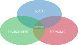
An overview of wetland/water permitting in Minnesota

Alison Harwood, Director of Natural Resources, WSB

Wetlands and other waters in Minnesota are regulated by a variety of agencies, including those at the federal, state, local or watershed level. Knowing who to contact and what type of approvals are needed is important and depends on the scope and location of the project.

Federal level

At the federal level, the U.S. Army Corps of Engineers (COE) regulates discharge of fill to waters of the U.S. and works within the channel of navigable waters as defined by Section 10 of the Rivers and Harbors Act. If work is proposed within a water of the U.S., a permit may be required through Section 404 of the Clean Water Act. Project impacts will fall into one of the following permit categories:

  • Regional General Permit (GP): These permits are issued for projects that impact less than 0.5 acres of wetland and authorize a specific list of impacts, or authorize work that is regulated and approved by the Minnesota Department of Natural Resources (DNR) through the Public Waters program. It typically takes three to four months to obtain this permit. In Minnesota, approval with a GP automatically includes EPA/MPCA Section 401 Certification.
  • Letter of Permission (LOP): These permits are issued for projects that impact wetlands between 0.5 to three acres (non-road projects) or 0.5 to five acres (road projects). COE performs an environmental assessment, taking four to 12 months to obtain this permit. In Minnesota, this approval automatically includes EPA/MPCA Section 401 Certification.
  • Individual Permit (IP): These permits are issued for projects that exceed the thresholds for the GP and LOP. COE performs an environmental assessment, taking anywhere from nine months to two years to obtain this permit. EPA/MPCA Section 401 Certification must be obtained separately.

State level

At the state level, the DNR regulates areas below the Ordinary High Water (OHW) of wetlands and waters listed as Public Waters. (View maps of DNR Public Waters. Obtain the OHW elevation from the DNR Area Hydrologist.)

If work is proposed below the OHW of a public water, a Public Waters Work permit will be required, which typically takes 60 to 90 days to obtain. It can take longer to obtain the permit depending on the complexity of the project. The DNR also issues permits for other types of work within public waters, including docks, crossings, dewatering, dredging, and boat launches.

Local level

At the local level, the State of Minnesota issued MN Rule 8420, the Wetland Conservation Act (WCA). (Guidance can be found here.)

The objective of the WCA is to obtain no net loss of wetlands within the state. The rule is administered at the local level by a local government unit (e.g., the city, county, watershed district, or soil and water conservation district.

If a project will impact a wetland, an approval through the Wetland Conservation Act is likely necessary. There are several types of approvals that may apply to the project:

  • No loss: Indicates that the wetland will not be impacted by the project (e.g., temporary impacts, impacts to incidental wetland).
  • Exemptions: Various exemptions exist for projects that are required to maintain public health and safety but also may result in minor wetland impacts.
  • De minimis: Allows a minimal amount of wetland impact to occur depending on the location of the wetland impact within the state.
  • Replacement plan: Allows wetland impacts to occur given that no other alternatives exist, impacts have been minimized to the extent practicable, and impacts will be mitigated (e.g., replaced).
  • Road bank replacement: Allows the state to replace for impacts to wetlands required due to the reconstruction of an existing serviceable public roadway to meet safety or design standards. This program is available to city, county, township, and other local road authorities. It is not available for Minnesota Department of Transportation projects.

To obtain any of the above permits, an applicant must provide project information that includes a project purpose and need, alternatives analysis, impact minimization measures, and a mitigation plan. Typically, mitigation is required at between a 1:1 to 2.5: 1 ratio.

Some watershed districts within the state also have regulatory authority over the waters within their watershed. Though each watershed district has their own specific rules, they typically cover impacts resulting from stormwater, erosion, dredging, wetland impacts, and floodplain fill. (Determine which watershed district a project is located within.)

What does this mean for a project?

If a project has the potential for water resource impacts, it is best to start coordinating with the applicable regulatory agencies as soon as possible (ideally a year in advance of construction). If you are unsure of whether your project will impact wetlands, begin by contacting your local WCA representative, Army Corps of Engineers regulatory department, and/or DNR Area Hydrologist.

Sustainable Design

By Steven Foss
Feb. 6, 2015

Our environment – natural and built – is a complex network of components, creating unique and dynamic landscapes. Sustainable design focuses on maintaining and improving environments through a collaborative approach, considering how they fit within the greater ecosystem, and employing devices that are environmentally conscious and friendly. Sustainable design strategies typically include reducing carbon footprints; improving energy efficiency; and enhancing or protecting natural habitats while still providing economic, environmental, and social benefits.


Environmental benefits of sustainable design

The major goal of sustainable design is to preserve and improve our environment while reducing our carbon footprint and minimizing the use of natural resources. When sustainable design solutions are incorporated through project development, communities and the environment benefit through one or more of the following scenarios:

  • Protecting/conserving the ecosystem
  • Improved air and water quality
  • Reduced volumes of waste
  • Conserving natural resources

Social benefits of sustainable design

Implementation of sustainable design not only provides environmental benefits to our communities, but also improves our quality of life, health, and well-being. Improving the environment and integrating sustainable practices can have the following results on individuals and communities:

  • Improved active and passive spaces for social interaction and circulation
  • Improved emotional function
  • Reduced stress
  • Improved work effectiveness
  • Stronger sense of belonging and connection to the environment

Economic benefits of sustainable design

Incorporating sustainable design, through integrated design processes and innovative use of sustainable materials and equipment, can also generate economic benefits such as:

  • Reduced infrastructure needs
  • Lower annual costs for energy, water, and maintenance/repair
  • Reduced “heat island” effect
  • Improved ability to attract new employees/residents
  • Reduced time and cost for project permitting
  • Improved use of former sites (such as brownfields)
  • Reduced construction costs through reuse of construction materials
  • Increased property values

Summary

Sustainable design transforms conventional thinking about our landscape, infrastructure and buildings. It presents significant opportunities to improve our quality of life through environmental, social and economic benefits.

The following is a list of materials and tactics that can be incorporated into sustainable design practices:

  • Preserving existing tree cover and biodiversity
  • Vegetated swales/rain gardens
  • Dry and wet ponds
  • Green roofs
  • Underground storage and permeable pavement
  • Enhanced tree plantings (Silva Cells)
  • Infiltration devices
  • Alternative energy (wind, solar, biomass, geothermal, hydroelectric)
  • Conversion of mowed/maintained turf to low-maintenance native grasses
  • Stormwater capture and reuse for irrigation
  • Use of recycled construction materials


The Alphabet Soup of Minnesota Environmental Review: EAWs, AUARs and EISs

by Andi Moffatt
Feb. 6, 2015

Acronyms

  • AUAR: Alternative Urban Areawide Review
  • EAW: Environmental Assessment Worksheet
  • EIS: Environmental Impact Statement
  • EQB: Environmental Quality Board
  • MEPA: Minnesota Environmental Policy Act
  • NEPA: National Environmental Policy Act
  • RGU: Responsible Government Unit

Introduction

The Minnesota Environmental Policy Act (MEPA) and Minnesota Rules 4410 require some projects to undergo environmental review prior to obtaining permits or approvals. The purpose of this review process is to avoid and minimize damage to environmental resources (Minnesota Rules 4410.0300). The Environmental Quality Board (EQB) promulgates rules and provides guidance to the state’s environmental review program. This article provides information about the Minnesota environmental review process, discusses some triggers for environmental review, and discusses general timelines for the process.

Background

The MEPA was enacted in 1973. It was modeled after the federal National Environmental Policy Act (NEPA), but written to specifically address other projects the state, public, and agencies deemed to need environmental review.

Three documents are the basis for Minnesota’s environmental review program:

  • Environmental Assessment Worksheet (EAW)
  • Environmental Impact Statement (EIS)
  • Alternative Urban Areawide Review (AUAR)

All three documents generally analyze similar topics for a given project, including stormwater management; wetland, habitat and fisheries; water and wastewater; traffic; air; noise; cultural resources; pollutant sources; and impact to infrastructure and the environment. The main difference between the documents is the extent and level of analysis needed.

The EAW is the heart of the state’s environmental review program. The purpose of the EAW is to determine if an EIS is needed. The EAW is intended to be a basic document, while an EIS goes into much more detailed analysis and investigation and is required if a project meets a mandatory EIS threshold or if the EAW cannot adequately gauge the possible environmental impacts of a project.

An AUAR can be thought of as a hybrid between an EAW and an EIS. While an EAW and EIS are used for specific projects (e.g., a big-box retailer proposing to develop within a city), an AUAR is used to analyze different development scenarios where a specific development is not known. Cities can use AUARs to analyze general development of a section of their city, understand possible impacts of the development, and identify specific mitigation measures. An AUAR can also be used for certain specific development plans that may trigger an EIS as an alternative to the EAW; however, there are additional review steps in these unique cases. Additionally, some types of development, such as heavy industrial development, cannot use the AUAR process.

The table below generally summarizes when to use each document.

      EAW        EIS        AUAR
  • Project with a specific development plan
  • Required by Minnesota Rules 4410
  • If petition for review is granted
  • RGU discretion
  • Project with a specific development plan
  • Required by Minnesota Rules 4410
  • EAW determines it is necessary
  • Projects with significant impact
  • Projects with undefined development plan
  • Large tract of land anticipated to develop
  • Can be used in some cases if EAW or EIS is required (check rules beforehand)


Environmental review triggers

There are many different triggers for a mandatory EAW or EIS, which depend on factors such as the location of a project, the type of project, and the city where the project is located. Common EAWs or AUARs include reviews for new residential development, construction of light industrial or commercial areas, new sanitary sewers of a specific capacity, some road projects, and projects that have large impacts to wetlands or water bodies. A full listing of the environmental review triggers can be found here.

The public can also petition to have an EAW completed for a project. In this process, a petition must be submitted to the EQB with at least 100 signatures. The EQB reviews the petition for completeness and submits it to the RGU for technical review and a final determination.

Timeline

Timelines will always depend on the specifics of an individual project or review. A general rule of thumb, however, for the time it takes to develop these documents is as follows:

  • EAW: 3-5 months
  • EIS: 1-3 years
  • AUAR: 1 year

Who completes the document?

The rules specify the RGU for each type of project. It is often the land use authority (a city or county) but could also be the Minnesota Pollution Control Agency or another agency. The project proposer is required to supply certain information to the RGU to complete the document. The RGU is responsible for making sure it is accurate and complete. We have seen this process work in one of two ways: sometimes, the RGU prepares the document with information provided from the project proposer; in other instances, the project proposer prepares the document and then the RGU reviews and finalizes it. Both ways are acceptable.

Review process

Once a document is complete, it is submitted for a 30-day public comment period and is sent to the required review agencies. After the comment period, responses will be prepared.

For an EAW, a Findings and Conclusions document is prepared for the RGU decision-making authority, such as a City Council, which is tasked with reviewing the document and preparing a Record of Decision on the Need for an EIS.

For an EIS or AUAR, a final document is prepared that includes revisions based on the comments received prior to going to the RGU decision-making authority.

What does this mean for you?

Check the required triggers for an environmental review early in the project proposal process. A project’s timeline may be impacted by required reviews. Additionally, there is a prohibition on governmental approvals and construction until the environmental review process is completed.

Complete information can be found at the Minnesota Environmental Quality Board website.

Wildlife Passage Bench

By Roxy Franta
February 1, 2016

A passage bench, or “critter crossing,” is a gravel walking path incorporated into the riprap along a bridge abutment to allow wildlife to pass under bridges uninterrupted. Many species of wildlife travel along the natural shoreline of streams, but modern infrastructure often breaks the continuity of the shoreline. Traditional riprap is not passable by many animals, forcing them to leave the shoreline and cross at busy bridge approaches. Wildlife on roadways presents safety hazards to both the animal and drivers, but including a passage bench into bridge design is an easy solution to this common problem in Minnesota.

(photo credit: Minnesota Department of Natural Resources)

Why include a passage bench?

The idea of a passage bench was developed by the Minnesota Department of Natural Resources (DNR), the U.S. Fish and Wildlife Service (USFWS), and the Minnesota Department of Transportation (MnDOT) in 2005. Continued observations prove this feature to be successful, providing benefits such as:

  • Movement of animals under the bridge, increasing road safety of bridge approaches
  • Safe footing for bridge inspectors and fishers
  • Access for maintenance
  • Flexibility in design for cross-section of normal channel and flood profile
  • Riprap design change from aggregate base to geotextile base
  • No extra cost or time to install
  • Wildlife conservation by minimizing deaths from collision

Designing a bench

In 2011, the passage bench became part of the MnDOT Standard Plan Set for use on all bridges. Specifications for passage bench design can also be found in the “Best Practices for meeting DNR General Permit 2004-0001, March 2006” guidelines.

The passage bench is a level trail from one side of the bridge to the other. It should be constructed of any size aggregate that is “walkable,” to allow wildlife proper footing as they pass under the bridge. The bench should be placed at or slightly above the adjacent bank elevation to create a continuous path that mimics the natural contours of the streambank and should be tied into the groundline outside the bridge area. A typical game trail width of three feet has proven to be successful for animal movement.

Common mistakes

The passage bench is a relatively simple addition to bridge construction, but there are some common mistakes to avoid during installation.

  • Having the riprap block the path. It’s important to incorporate the passage bench into both the grading and bridge plans to ensure it is completed and continuous across the entire area. Drainage outfalls and associated riprap along the abutment should be placed below the bench.
  • Too high or too low. The height of the passage bench often doesn’t match the natural streambank. A good indicator for the bench elevation is to place it at or just above the vegetation line.
  • Lack of guidance for wildlife. Though not a requirement in Minnesota, the right-of-way (ROW) fence should be used to guide wildlife to the passage bench. ROW fencing is often extended parallel to the roadway until it reaches the stream at the bridge. Instead, the fence should be turned up at the abutment and installed tight against the bridge corner. If it is a divided highway, a median fence should be installed as well.
  • Too skinny. MnDOT specifications suggest a minimum bench width of three feet. Benches that are too narrow are subject to longitudinal scouring during flood events and are not used as often by wildlife.
  • Construction phasing. Contractors often wait to install the passage bench until all other work is complete, but this makes it impossible to mechanically install it once the bridge beams are set in place. Installation should occur with riprap installation and should be a planned part of construction phasing.

Success

MnDOT funded a study of the passage bench and collected data on wildlife movement and utilization in 2009. They concluded that a wide variety of species use the passage including black bear, red fox, gray fox, bobcat, whitetail deer, and even humans.

Roadway networks have caused fragmentation in the natural environment, but as a construction planner, design engineer, or contractor, you can help minimize this conflict between wildlife and highway operation with the inclusion of a passage bench.

Resources:

What Makes a Wetland a Wetland?

By Joe Handtmann
June 10, 2015

A wetland is a flooded area of land with a distinct ecosystem based on hydrology, hydric soils, and vegetation adapted for life in water-saturated soils. Wetlands are heavily protected by federal, state, and local policies due to their environmental benefits and the historical filling and dredging that removed more than 50 percent of them across the country. Wetland types vary based on their location. Mangroves are found along the shores of salty waterbodies while peat bogs are found in cool climates, where slow decomposition facilitates the accumulation of peat over long periods of time. Common wetlands in Minnesota include wet meadows, shallow and deep marshes, scrub-shrub wetlands, and bogs.

Requirements and delineation
To be considered a wetland, the site must have the presence of water, soils indicative of frequent and prolonged flooding, and vegetation suited to handle flooding or saturated soils. Determination of wetland boundaries must be done by a certified wetland delineator based on the Army Corps of Engineers Wetland Delineation Manual and appropriate regional supplements. Delineations are subdivided into levels. Level one means onsite inspection is unnecessary; level two means onsite inspection is necessary; and level three, which is a combination of levels one and two.

Hydrology
Identifying hydrology, or presence of water, can be as simple as noticing the sustained presence of water in boreholes or manually measuring surface water, or as difficult as requiring the use of continued monitoring wells and piezometers. Areas with a surface water depth of more than 6.6 feet are considered deepwater aquatic habitats and not wetlands.

Hydric soils
Soils that are saturated for a long period of time display common visual patterns identifiable in a soil profile. Soils developed in anaerobic conditions show unique colors and physical characteristics that are indicative of hydric soils. When water continuously saturates the ground, organic soils are likely to occur. Organic soils are referred to as peats or mucks and require more than 50 percent of the upper 32 inches of soil to be composed of organic material. Hydric mineral soils form under a range of saturated conditions, from permanently saturated to seasonally saturated. Indicators for hydric soils can be found in the Field Indicators of Hydric Soils in the United States guide, published by the USDA.

Hydrophytic vegetation
Wetland vegetation is classified by its ability to survive in saturated soil conditions. These classifications range from OBL (obligate wetland plants that usually occur in wetlands), to FAC (facultative plants that occur in wetlands and non-wetlands equally), to UPL (obligate upland plants that are rarely found in wetlands). When OBL, FACW, and FAC species make up the vegetative species at a site, then the site is considered to have hydrophytic vegetation.

Classification
Two main systems are used to classify wetlands in Minnesota – the Circular 39 and the Cowardin systems. Both systems are commonly used when writing permit applications or describing or writing about wetlands. A noteworthy exception is the case of the National Wetlands Inventory, for which the U.S. Fish and Wildlife Service exclusively used the Cowardin system.

Circular 39
The Circular 39 system was developed by the U.S. Fish and Wildlife Service in 1956, and divides wetlands into eight different types based on water depth and variety of vegetation.

  • Type 1: Seasonally Flooded Basin/Floodplain Forest: Soils are flooded during variable seasonal periods. Often found in upland depressions, these wetlands are well-drained during the rest of the year. Vegetation can be quite variable.
  • Type 2: Wet Meadow, Fresh Wet Meadow, Wet to Wet-Mesic Prairie, Sedge Meadow, and Calcareous Fen: Soils in these wetlands are usually without standing water, but saturated close to the surface. Vegetation includes sedges, grasses, rushes, and broad-leaved plants. These wetlands are notes for their wildlife habitat capabilities.
  • Type 3: Shallow Marsh: Shallow marshes are covered with more than six inches of water throughout the year. Typical vegetation includes grasses, cattails and bulrushes.
  • Type 4 – Deep Marsh: Similar to shallow marshes, deep marshes are covered in water from six inches to three feet deep. Cattails, reeds and lilypads are common.
  • Type 5: Shallow Open Water: Water is present, but less than six feet deep and fringed with emergent vegetation. This type of wetland is often used for fishing, canoeing and hunting.
  • Type 6: Shrub Swamp; Shrub Carr, Alder Thicket: Soils are heavily saturated and may be covered in up to six inches of water. Dogwoods, willows and alders are all common species.
  • Type 7: Wooded Swamps; Hardwood Swamp, Coniferous Swamp: Typical trees in wooded swamps include tamaracks, white cedar, arborvitae, black spruce, balsam, red maple, and black ash. The prevalence of trees helps control water flow during flood events. Soils are saturated up to a few inches of the surface and may be covered by up to a foot of water.
  • Type 8: Bogs; Coniferous Bogs, Open Bogs: Organic soils are prevalent in bogs, with continually waterlogged soils and a spongy covering of mosses. Shrubs, tamaracks, mosses, and black spruce are all common species.

Cowardin
The Cowardin system was developed in 1979 for the U.S. Fish and Wildlife Service to classify wetlands and deepwater habitats. This system was used in the National Wetlands Inventory to identify wetlands. Two major wetland types, coastal and inland, are identified. All Minnesota wetlands are defined as inland (palustrine), which is then subdivided based on vegetation classes and bed material.


Integrated Design Approach

By Robert Slipka
Feb. 6, 2015

Integrated design brings together a diverse team of design professionals on one project. Projects benefit from this approach because a wider range of experts is contributing throughout the project as a team, rather than acting independently.

Early integration is crucial to reduce the potential for expensive conflicts as design progresses or implementation begins. The integrated design approach involves all parties, including design professionals, clients/owners, permitting agencies, and others. Involvement may also include cost analysis specialists, construction managers, and contractors.

No matter what that project type, an integrated approach helps ensure a holistic outcome rather than a culmination of interdependent elements. Below are two examples of what teams could look like.

Example 1

A site development project is led by a landscape architect or civil engineer with direct integration of specialists such as environmental scientists, ecological specialists, engineers, building architects, electrical engineers, irrigation designers, and the client (including their operations and maintenance staff).

Example 2

A roadway corridor project is led by a transportation engineer and/or a planner. The team for this type of project may integrate urban designers/landscape architects, engineers, environmental scientists, right-of-way specialists, and representatives from numerous government agencies.

Design charrettes and brainstorming sessions are often utilized heavily in the beginning phases of project planning and design. This helps the team identify key goals, strategies, and desired outcomes of the project while also establishing areas of conflict or design implications. Including a diverse range of professionals means a better likelihood of achieving creative solutions that might not be explored in a conventional, non-integrated approach. As the project develops into the construction documents phase, continued collaboration is required to ensure compatibility of spatial character, uses, spaces, materials, and other factors. This approach can also identify conflicts that might not otherwise be identified until late in design or into construction, avoiding unanticipated costs or redesign.

Although an integrated approach provides better results, it is important for consultants and clients to judge how extensively integration needs to occur based on costs and benefits. Some projects are smaller in scale or fee, which can make an elaborate integrated approach difficult to justify. Clients should also be aware that the term “one-stop shop,” often utilized to describe multi-disciplinary firms, does not necessarily mean that an integrated design approach is used for projects. If it is unclear or unproven, clients should ask the consultant to describe how the various team members will be integrated throughout the design process. The ultimate goal is to achieve higher quality projects with increased cost effectiveness to clients.